วันพฤหัสบดีที่ 13 พฤษภาคม พ.ศ. 2553

Product Detector for SSB and CW

General purpose receivers have a diode detector, usually fitted for AM reception (and often to supply an automatic volume control voltage for an early IF amplifier). This type of detector can only operate well with CW or SSB when signals are not so strong that they swamp the BFO carrier. The experimenter or constructor may thus wish to provide a product detector, and Figure 29 can be used.


Two inputs are required to the FET. That to C1 is taken from the secondary of the final IFT in the receiver. C4 is connected to 3 in Figure 28

The audio filter is optional, and is designed to reduce the higher frequencies, not necessary for communication purposes. If employed, it can have two 2nF capacitors, with a 100mH choke. The choke, if not screened, should not be located where it may pick up hum from a mains power supply.

After adding this detector, a slight readjustment of the tuning of the final IFT may be necessary. The associated BFO or CO is used in the manner already explained.

Where resolution of strong SSB signals fails merely because the transmission is too strong, an easy solution to this difficulty can be found in fitting an aerial attenuator. Figure 7 shows how a potentiometer can be employed, with no changes to receiver circuits.

1.6MHz Beat Frequency Oscillator

To resolve SSB or CW, a BFO signal may be coupled into the intermediate frequency amplifier. In these circumstances, the BFO has to operate near the intermediate frequency of the receiver, for transmissions of all frequencies. So with a BFO of this type, signals may be received at any frequency throughout the ranges which are provided for the receiver.

Some short wave receivers have an IF of about 1.6MHz. The BFO must then be constructed for this. With most general purpose or ordinary domestic receivers, the IF is near 455/470k Hz. If so, the BFO has to be arranged with this in view. Except for this point of providing the correct frequency, both 1.6MHz and 455-470kHz BFO units are the same, and employ the circuit in Figure 28.

455-470kHz Beat Frequency Oscillator

A general purpose RF FET is used as oscillator, Its frequency is determined by VC1, with the associated winding and parallel capacitor. The smaller winding is for drain feedback. A stabilised supply with 6.2v 400mW Zener diode allows the unit to be run from the receiver, if wished.

For frequencies around 1.6MHz, a Denco (Clacton) IFT17 intermediate frequency transformer is used. For frequencies in the 455-470kHz range, the IFT14 is fitted. Each has the parallel capacitor present inside the screening can, in the usual way, and pin connections are shown in Figure 28.

Components may be assembled on a small insulated board, and it may be possible to fit this somewhere inside the receiver. An on/off switch is included in the positive supply lead, as the BFO must not be in use for ordinary AM reception.


A control knob is necessary on VC1, as this must be adjustable during reception. If it is not practical to include this control on the receiver, then the BFO can be constructed as a separate unit.

The best degree of coupling from 2 of the BFO coil to the receiver IF circuits needs to be found by trial. It should be, sufficient to run an insulated lead from 2, to the vicinity of the first transistor in the IF amplifier. Alternatively, a capacitor of 8.2pF can be included here, as shown, and the output lead can be connected to the receiver diode, at the final IF transformer.

If coupling is too loose, only relatively weak CW or SSB stations will be resolved, and stronger SSB will sound like badly distorted and over modulated AM. However, very tight coupling is not wanted and will tend to swamp weaker transmissions.

Operation is similar to that described for the signal frequency resolver, except that as all signals are converted to the intermediate frequency in the receiver, it is only necessary to make trifling adjustments to VC1. For CW, VC1 will have two positions (above and below the station frequency). But for SSB, there is only one suitable frequency setting for the BFO, as if this is placed the wrong side the SSB signal, speech will be inverted, or unintelligible.

Initially, tune in an AM signal, and set VC1 to about half open position. Then rotate the core of the oscillator coil until a heterodyne is heard, and can be set to zero. Then rotating VC1 either way should cause an audio tone which rises in pitch. Check that this happens with signals on any frequency, to make sure harmonics of the BFO in the aerial circuit are not responsible.

Signal Frequency SSB/CW Resolver

Many general purpose receivers will have frequency bands which cover some of the amateur allocations, but which are not able to resolve single sideband or CW (Morse) signals. With a
communications type receiver intended for SSB or CW reception, a beat frequency or carrier oscillator is provided. With its aid, SSB or CW signals can be received. When a general purpose receiver is employed, the BFO or CO can be constructed as a separate unit.

The output of the BFO or CO may be taken to the intermediate frequency circuit of the receiver, as shown later. Alternatively, the beat frequency or carrier oscillator can operate at the frequency of the band being tuned. If so, no actual connection at all is necessary to the receiver, as the wanted signal and oscillator signal are both fed into the receiver aerial circuit.

This method is convenient for the low frequency amateur bands, especially 1.8-2.0MHz and 3.5-3.8MHz. It also has some advantage where the receiver tuning control is of a type which cannot easily provide critical tuning, as the latter will now depend on the signal frequency SSB/CW resolver.


The circuit in Figure 27 will operate at a fundamental frequency of approximately 1.75-2.0MHz, or 3.5-4.0MHz. The former range is suitable for both 160m and 80m, as the second harmonic of
the 160m range will provide resolution on the 80m band. However, the 3.5-4.0MHz coverage is more suitable when 80m alone is wanted, or some reception on perhaps 7MHz or 14MHz, with harmonics.

For the lower frequency range, C1 is 250pF and VC1 is 75pF. L1 has fifty-seven turns in all, tapped at twelve turns from the grounded end. The winding is of 32swg enamelled wire, on a 7/ 16th in or 11mm diameter former, with adjustable core. Turns are side by side. To cover the higher frequency range, L1 has thirty turns, tapped at 6 turns, with wire and former as described. C1 and VC1 are as shown.

Stabilisation of the oscillator can be omitted when the current is to be drawn from a separate battery, but becomes necessary if the circuit is operated from the same battery as the receiver. Otherwise fluctuations of supply voltage, especially at other than low loudspeaker volume, will cause frequency modulation of the oscillator.

Construction of the resolver should be in a metal case, with rigid mounting of components. A reduction drive is necessary for VC1.

As the output from the oscillator passes into the receiver aerial circuit, and is amplified with other signals, very loose coupling must be used. It may be found adequate merely to place the resolver unit near the receiver aerial lead. If more coupling than this proves necessary, a lead a few inches long can be taken from the tap on L1, out of the screening box, and near to the aerial lead. The, degree of coupling is not too critical. But if this is too great, signals will be swamped by the oscillator carrier. Alternatively, very loose coupling will give too low an input to the receiver, so that strong SSB or CW cannot be resolved.

To operate the unit, tune in the wanted SSB or CW signal with the receiver. Final tuning is now done with the resolver control, at the point where the oscillator signal is heard to beat or mix with the transmission tuned in. With CW, tuning is not too critical, as adjustments around the transmission frequency will merely alter the audio pitch. But for good reception of SSB, tuning is quite critical, as the resolver carrier should replace the carrier which was suppressed before transmission as correctly as possible.

Tight coupling of the oscillator is not necessary, and should not be made to an aerial, as this could cause interference to near by listeners.

วันจันทร์ที่ 10 พฤษภาคม พ.ศ. 2553

Modulated RF Generator

Adding T1, TR2 and associated items, shown in Figure 16, will allow modulation of the RF signal produced by the generator. The first stage in Figure 16 consists of the RF generator, as in Figure 15.

TR2 is an audio oscillator, with feedback from drain to gate by means of the transformer windings. A small driver transformer, as used to couple the driver stage to ½-watt and similar push-pull output stages in transistor portable and other receivers, will be found suitable for T1. The original primary is used for the drain circuit. The whole of the secondary is employed for the gate, the centre-tap being ignored. If no oscillation is secured, reverse the connections to one winding. It will be found that considerable control over the tone produced can be exercised by the choice of values for R1, R2 and C1. A clear tone of middle frequency (say 400 hertz) is most satisfactory. TR2 is a general purpose or audio FET.


The RF produced by TR1 will now be heard to carry an audio tone, so can be tuned in by ear with a receiver. For trimming and similar adjustments, take the generator output to the aerial circuit of the receiver, or to a loop of a few turns near or on its ferrite rod. Signal level must be kept down with VR1, or the receiver automatic volume control response will mask exact adjustments.

RF Signal Generator

A signal generator is a most useful instrument for aligning and checking the RF and IF sections of a receiver. Figure 15 shows the RF section of a generator, to which modulation can be added as explained later.

L1 and VC1 can be selected from a wide range of values, tosecure the coverage required. It is convenient to fit the Denco(Clacton) “Red” oscillator coils, of valve type. With these, pin 8 is taken to drain (S1) and pin 9 to C1. Pin 1 goes to S2 for all coils except Range 1, when pin 7 is used. The appropriate ground pin for each range is as shown below, which indicates the bands over which these coils can be used, with a capacitance swing of approximately 20-350pF for VC1.

Range 1. ( 5 ) 380 - 1600kHz.
Range 2. ( 2 ) 0.8 - 3.5MHz.
Range 3. ( 3) 2 - 8.5MHz.
Range 4. ( 4 ) 6 - 22MHz.
Range 5. ( 6) 15 - 45MHz.


If other coils are used, allowance has to be made for the omissionof the usual padders and trimmers, as well as for the difference in receiver aerial and oscillator frequencies.

S1/S2 can have as many ways as bands required. However, the higher frequency coils need short connections, and coils must be reasonably separated from each other. Numerous general
purpose and RF type FETs will be found suitable. The presence of oscillation throughout each band can be checked with a meter in one battery lead - current should change if VC1 is shorted. The drain feedback winding must be correctly phased to obtain oscillation.

VR1 is an output attenuator. Construction should be in a metal cabinet, with a reasonably large scale for VC1. Calibration can be by the methods described later.

The signal produced by this generator is unmodulated, or silent. Unmodulated RF is used for tuning sharp crystal filters, and can be used for alignment of receivers which have a tuning meter or indicator, or where a meter is clipped to the AVC circuit to show the effect of adjustments. For other purposes, it is necessary that an audio tone is present with the carrier or RF signal.

วันอาทิตย์ที่ 9 พฤษภาคม พ.ศ. 2553

S.W. Tuning Converter

This converter allows short wave reception with a receiver having a medium wave range which can be tuned to about 1.4MHz to 1.6MHz, or 1400-1600kHz. It has a single range, covering approximately 5 to 15MHz, or 60 to 20 metres, and this includes the most important short wave broadcast bands.

Two transistors are used, Figure 14. TR1 is the mixer, and TR2 the oscillator. Tuning is by the ganged capacitor VC1/2, and output at a fixed frequency in the 1.4-1.6MHz range passes to the receiver from TR1 drain at X.

L1 numbering is for the Denco (Clacton) “Blue” Range 4 aerial coil, L4 being the “White” (1.6MHz IF oscillator) Range 4 coil. Both are valve type coils. C4 is the oscillator padder, and it will be found that 960pF, 970pF or 1000pF may be used, though 960pF is specified by the coil maker.

Trimmers T1 and T2 can be integral with the ganged capacitor VC1/2, or may be separate trimmers of about 50pF.

It is convenient to use a layout in which L1 and TR1 are near the front section of the tuning, capacitor. VC1. L2 and TR2, with associated items, can then be adjacent to the rear section, VC2.


One of several possible methods can be used to couple the drain of TR1 to the receiver. A radio frequency choke between X and the positive line will allow capacitor coupling, as in Figure 7.
It is also feasible to provide a coupling winding on the receiver ferrite rod, as in Figure 12, or use an existing external aerial coupling winding here, in some receivers. A resonant coupling, as in
Figure 13, is also practicable, this being arranged for the frequency to be used with the receiver. This should not be too far removed from 1.6MHz or 1600kHz, or alignment difficulties can arise in the converter. If the receiver is of the type which must have an external aerial, it should not be too difficult to find a frequency near the high frequency end of the MW band where no unwanted signals break through. More care in finding a frequency may be necessary with a portable receiver with ferrite aerial, especially during the hours of darkness.

When a tuning position has been found on the receiver which gives no reception, note this for future use. Switch on the converter and align aerial and oscillator circuits in the usual way.

The low frequency band end reached depends largely on the position of the core of L2, while the high frequency band end depends on T2. Initially set L2 core at about middle position; with
T2 about half open. L1 and T1 must then be adjusted for best reception. L1 core is always adjusted near the LF end of the range, and T1 near the HF end. That is, rotate L1 core for maximum volume with VC1/2 nearly closed, and set T1 with VC1/2 nearly fully open.

Should L2 or T2 be altered, to modify the band tuned, then L1 and T1 will have to be readjusted to match.

If wished, T1 may be omitted, and a 50pF panel trimmer can be used instead. This will allow signals to be peaked up critically with any aerial, and eases alignment of aerial and oscillator stages.

With an RF amplifier having two tuned circuits (as example,Figure 10) both coils must tune simultaneously to the same frequency. But in Figure 14 L1 and L2 must maintain a frequency
difference throughout the tuning range, this corresponding to the output frequency at X. As example, if the output is to be 1.6MHz, and L1 is tuned to 10MHz, then L2 is tuned to 11.6MHz. As far as possible, this same frequency difference should be maintained for all tuning positions of VC1/2. This is achieved by L2 being of lower inductance than L1, and by the series padder C4.

144MHz-2M Converter

The reception of 2 metre signals is generally with a converter and short wave receiver, preferably of communications type. The latter will have sensitivity and selectivity better than average. With such an arrangement of equipment, the 144MHz or other VHF signal is changed in frequency so that the converter output falls within the tuning range of the receiver.

A converter of this type often has its own RF amplifier, and a relatively low frequency crystal controlled oscillator, followed by frequency multipliers. This allows high sensitivity and excellent
frequency stability, but is a relatively complicated and expensive item. Bearing in mind that at this frequency the RF amplifier will not, contribute very much gain, and that tunable VHF oscillators
are used in many domestic VHF receivers, it is possible to use the much simpler circuit in Figure 13.


L1 is broadly tuned to the wanted frequency band by T1, and signal input is to gate 1 of TR1. TR2 is the local oscillator, and the operating frequency here is determined by L2 and T2. Oscillator injection is via C3 to gate 2 of TR1. The frequency of the output from the drain of the mixer TR1 is the difference between G1 and G2 frequencies. Thus if the signal at G1 is 144MHz, and TR2 is tuned to oscillate at 116MHz, output will be at 144 minus 116MHz, or 28MHz. Similarly, with the oscillator set at 116MHz, an input at 146MHz to G1 will give an output of 30MHz. Therefore 144-146MHz can be covered by tuning the receiver from 28MHz to 30MHz. L3 is broadly tuned to this band, and L4 couples the signal to the short wave receiver.

The oscillator can actually be tuned above or below the aerial circuit frequency of the converter, as it is the difference between converter signal input and oscillator frequencies which determines the converter output frequency. It is also possible to choose other reception and output frequencies, provided L1, L2 and L3 are chosen to suit.

L1 and L2 are wound in the same way, except that L1 is tapped one turn from its grounded end. Each coil has five turns of 18swg wire, self supporting, formed by winding the turns on an object 7mm in diameter. Space turns so that each coil is ½in or about 12mm long.

L3 is fifteen turns of 26swg enamelled wire, side by side on a 7mm former with adjustable core. L4 is four turns, overwound on the earthed (positive line) end of L3.

Layout should allow very short connections in the VHF circuits. A co-axial aerial socket is fitted near L1. A screened coaxial lead is preferred from L4 to the receiver, to avoid unnecessary pick-up of signals in, the 28-30MHz range. The converter will operate from a 9v to 12v supply.

L3 should first be peaked at about 29MHz. If a signal generatoris available (that described later can be used) couple this to TR1 drain by placing the output lead near the drain circuit. Tune
generator and receiver to 29MHz, and adjust the core of L3 for best results. Otherwise, couple an aerial by means of a small capacitor to the drain circuit, and tune in some signal in the 28- 30MHz range, to allow adjustment of the core of L3.

It is now necessary to tune L1 to about 145MHz, and L2 to 116MHz, or 174MHz. If an absorption frequency indicator is available, this will permit an approximate setting of T2. A dip oscillator will also allow T1 to be adjusted. (The circuits shown later may be used here.) Subsequently adjust L2 to bring the wanted signals in at the required frequencies on the receiver, and peak these for best volume with T1, and check the setting of L2 core.

The converter is best assembled in a small aluminium box, completely closed, which can be placed behind the receiver. Note that if TR2 is not oscillating, no reception is possible through the converter. TR2 should be a VHF FET, such as the BF244, MPF102, and similar types, and if necessary T3 may be adjusted to secure oscillation here. The 40602, 40673, and similar VHF types will be satisfactory for TR1. If needed, frequencies can be brought within the swing of T1 and T2 by stretching or compressing L1 or L2.

The aerial may be about 38½in long, constructed as a simple self-supporting or wire dipole, with a feeder descending to the converter.

Amateur activity is most likely to be greatest at week ends, and in many areas a whip or very short wire aerial will provide local reception.

Portable Receiver Booster วงจรขยายสัญญาณภาครับแบบพกพา

The range or volume of a domestic portable receiver can be increased considerably by adding an external aerial, and the circuit in Figure 12 does this, and provides a tuned booster stage also. With an external aerial, this can allow a small transistor portable or similar receiver to give good reception of signals which may be virtually inaudible otherwise. The booster is not required for normal or local reception, and it is not permanently connected to the receiver in any way.

Medium Wave coverage is most useful, and the coil connection numbers are for the Denco (Clacton) “Blue” Range 2 valve type coil. This can be fitted in a 9-pin valveholder, or can be mounted by its threaded end, with leads soldered directly to the pins. Coverage in this circuit is approximately 1.6MHz to 550kHz, but can be varied to suit the receiver by altering the position of the coil core.


TR1, R1, C1 and C2 can be assembled on a small insulated board, fitted near VC1 and the coil. Two thin flexible leads run from TR1 drain and C2 (positive) to the coupling loop L1. This consists of fifteen turns of insulated wire, about 1in in diameter. Wind these turns on a suitable object, slip the winding off, and bind it with cotton to keep the turns together. Connections from
the booster to the loop should not be unnecessarily long - about 6in to 9in or so. The loop and its leads may all be one uncut length of thin flexible wire.

If it is convenient to place L1 on the receiver ferrite rod, without in any way disturbing the existing windings there, this provides the closest coupling. Otherwise, position L1 near the rod and its medium wave coil, but outside the receiver. Tune in a weak signal, with VC1 adjusted to peak this up to best volume, and check that L1 is providing effective coupling, as shown by best sensitivity. It is necessary to operate VC1 in conjunction with the receiver tuning, so its scale can be calibrated to agree with the receiver, by tuning in transmissions throughout the band.

L1 and the receiver should not be placed so that there is coupling back to the aerial coil or aerial, or instability may arise. This will cause whistles on all signals.

Best signal pick up will be by an outdoor aerial, and this can be some 20ft to 50ft or so of wire, as high and clear of buildings as possible. However, even a poor or short indoor aerial can be expected to give an increase in volume, especially if an earth connection is also available.

Ham Band Preselector

An amplifier or preselector is often used to improve the reception of amateur signals. By employing a selection of series and parallel capacitors, it is possible to arrange that each band shall completely fill the tuning scale. However, this does not contribute anything in terms of efficiency, and can be tiresome to adjust. For these reasons, tuning here is with the single capacitor VC1, with parallel fixed capacitor C2. Values are chosen to accommodate the largest band, so there is coverage to spare on the smaller bands. This is of little or no disadvantage in practice, since tuning of the preselector is merely to peak up the wanted signals in each band.

The amateur bands are as follows: 1.8-2.0MHz (160 metres), 3.5-3.8MHz (80 metres), 7.0-7.1MHz (40 metres), 14.0-14.35MHz (20 metres), 21.0-21.45MHz (15 metres), 28.0-29.7MHz (10 metres). Outside Great Britain some of these frequencies are extended.


In Figure 11, a 2-pole 6-way switch selects the required coils, for 160, 80, 40m and other bands. Signal input is to gate 1. The potentiometer VR1 provides a gain control, to avoid over-loading of the receiver with strong signals. Drain and source circuits are arranged as in Figure 7, with capacitor coupling to the receiver. If the drain circuit were also tuned, twelve coils would become necessary, with ganged tuning.

Winding of the six aerial coils is not too critical, as it is only necessary to set the cores so that amateur signals throughout each band can be peaked by VC1. All coils are wound on formers approximately 9/32in or 7 mm in diameter, and 1in long.

  • 10m. Seven turns 26swg side by side. Aerial coupling four turns.
  • 15m. Nine turns 26swg side by side. Aerial coupling five turns
  • 20m. Fifteen turns 32swg side by side. Aerial coupling eight turns.
  • 40m. Twenty eight turns 32swg side by side. Aerial coupling fifteen turns.
  • 80m. Sixty turns 34swg side by side with two cores. Aerial coupling thirty five turns.
  • 160m. 120 turns in compact pile occupying ¼in width, 34swg. Aerial coupling 60 turns in pile.
Details of coil winding will be found earlier. It is important that windings are not covered with adhesive, cement, or other substances. Winding should begin very near the top of the formers, to give clearance from a metal chassis if inductors are mounted on it. At least one winding diameter should be left between any metal and the coil (say ½in minimum).

Layout should place the switch near VC1 and G1, and should permit very short connections for 10m, 15m and 20m coils in particular.

In view of the number of turns required for 160m, it may be noted that a receiver type medium wave band coil can often be used here. Some coils of this type will reach 160m with the core screwed fairly well out. If not, some turns need to be removed. A Litz wound coil here will give some improvement in efficiency.

11-32MHz MOSFET Stage

This can have similar applications to the circuit in Figure 9, but uses a dual gate FET, Figure 10. Such a stage can provide a very useful degree of gain. It becomes necessary to screen or segregate gate 1 input and drain output tuned circuits.L2 and L3 each have eleven turns of 26swg enamelled wire,side by side on a 7mm cored former. With a 2-gang 100pF capacitor for VC1/VC2, coverage is approximately 11 to 32MHz. Trimmer T1 and T2 can each be 20pF.

The coils are wound as described for Figure 9, and alignment of the two tuned circuits is also carried as described there. L1 has five turns, and L4 four turns, situated as explained for Figure 9.

TR1 operates with fixed gain. If a gain or sensitivity control is wanted, this can be added as shown in other circuits. An aerial input potentiometer may be added (Figure 7) or gate 2 voltage can be adjusted by a potentiometer


A gain control is not likely to be necessary when the stage is used before a receiver which has its own RF gain control. Otherwise, overloading of early stages of the receiver may arise with strong signals.

Alternative forms of output coupling are shown. If L4 is used, one end is grounded (see Figure 9) and Y is connected to the aerial input socket of the receiver. This method is preferred where the receiver has the usual medium or low impedance input. Some receiver have a high impedance aerial socket for end fed and similar aerials which are arranged for high impedance feed, and with these results will be improved by not using L4, instead, C4 provides capacity coupling to the aerial socket at X. Trimming and alignment of L2 and L3 should be checked after adding this connection and C4.

The 40602 or 40673 will perform well here, though other dual gate FETs can be fitted with satisfactory results.

Segregation of circuits is most easily achieved by using a small metal chassis, with L1/L2 on top, near VC1/2. A lead can then pass down through the chassis from VC1 to G1. TR1 and associated
items, including L3/L4, can be under the chassis. This screens L3 from L2. The RF connection from X or Y to the receiver should be short, and away from the aerial lead to L1.

13-30MHz Grounded Gate Stage

If a receiver has an intermediate frequency of 455 to 470kHz, second channel interference is always present at frequencies higher than about 15MHz, unless one or more tuned RF stages are included. This trouble arises because the second channel is so close to the wanted frequency. As example, if the receiver is tuned to 20MHz, or 20,000kHz, and the receiver IF is 470kHz, then the oscillator will be operating on 20,000 plus 470 = 20,470kHz. However, unwanted signals which are 470kHz higher in frequency than the oscillator will also be converted to 470kHz. As a result, transmissions around 20,940kHz or 20,94MHz will be passed through the receiver, in this instance, as the aerial circuit will not reject these, when tuned to 20MHz. This effect, with a superhet, can only be avoided by raising the intermediate frequency, or providing additional selectivity before the mixer or frequency changer. The grounded gate stage in Figure 9 introduces two additional tuned circuits before the mixer, so is of considerable aid in reducing interference from second channel signals. By keeping parallel capacitances to a low value, approximately 30MHz to 13MHz can be tuned in a single band, with good efficiency.


L2 and L3 are identical, and are wound with 24swg enamelled wire, using 7mm formers with adjustable cores. The cores must be suitable for use at 30MHz or higher frequencies. L2 and L3 are each eighteen turns, but L2 is tapped at three turns from the grounded end for C1 and R1. Begin winding from near the top ends of the formers, securing the wire with a spot of adhesive. Turns are side by side. L1 is wound immediately below the grounded end of L2, and has seven turns. L4 is wound at the grounded end of L3, and has five turns.

Layout should place L1/L2 at one side of the ganged tuning capacitor VC1/VC2, and L3/L4 at the other side. The output lead from L4 and ground line are connected to the aerial terminal and chassis or earth of the receiver. It may be possible to draw a positive supply from the receiver, 9v to 12v being required here.

No connection must ever be made to the chassis of an AC/DC type receiver which draws current directly from the mains, and may thus have a live chassis.

To obtain maximum band coverage without increasing VC1/2 in value, T1 and T2 must be set at low values. First unscrew T1 and T2 completely. Set the cores of L2 and L3 in approximately similar positions. A signal should then be tuned in around 28-30MHz, and T1 or T2 can then be adjusted for best volume. Subsequently find a stable signal around 14-16MHz, and set the cores for best volume. These adjustments should be repeated a few times, adjusting T1 and T2 at the HF end of the band (VC1/2 nearly fully open) and the coil core towards the LF end of the band (VC1/2 nearly closed).

It the receiver has a signal strength or tuning meter, this will aid critical alignment. Alternatively, choose weak signals or if possible switch off the automatic volume control circuits, so that AVC action does not mask adjustments.

Should a receiver with no RF stage be in use, check that the grounded gate stage is actually being tuned to the correct signal frequency, and not to the second channel, as second channel signals may come through strongly with such a receiver.

With receivers having an IF of 1.6MHz, the second channel will fall at 3.2MHz from wanted transmissions, so is less likely to be troublesome.

วันเสาร์ที่ 8 พฤษภาคม พ.ศ. 2553

Top Band Preselector

The 160 metre band carries amateur and other signals, and Figure 8 is a preselector for approximately 1.8MHz to 2.0MHz. Here, VC1/2 is a 2-gang capacitor, and thus two additional tuned circuits are obtained ahead of the receiver. It is necessary to tap the gate of TR1 down L2, to preserve stability. However, screened coils are not essential, if L1/L2, and L3/L4 are situated at opposite sides of the ganged capacitor and arranged to avoid unnecessary feedback or coupling.


C1 and C3 are best 2% or similar silver mica. All HF and general purpose FETs suitable for RF use should prove suitable here. Values ale for the 2N5459 but will suit similar devices. Both coils are wound on cored formers approximately 10mm or 3/8in in diameter, and using 32swg enamelled wire. L2 and L3 each consist of fifty turns, side by side. Begin winding near the top of the former, securing the wire with “Bostik 1” or similar adhesive. The whole winding should not be covered with adhesive, varnish, wax or other substances. L1 is twenty turns, wound near the bottom of L2. L4 is similarly positioned, but has fifteen turns. It will couple into the usual dipole or similar receiver input socket, having a nominal impedance of about 75 to 300 ohms. Touches of adhesive will also hold these turns in position.


2N5459 PIN

A metal cabinet about 6 x 4 x 4 in is suitable for this unit. TR1 and R1/C2 can be wired on a small insulated board, fitted adjacent to VC1/2. C1, C3 and C4 can be soldered directly to the coil
tags. Separate trimmers for T1 and T2 are only required if the ganged capacitor does not have trimmers incorporated. Though VC 1/2 provides some bandspread a small bail drive or similar reduction drive should be fitted.

Medium Frequency Amplifier - improve long distance reception วงจรขยายภาครับย่าน MF ช่วยเพิ่มความไวให้ดีขึ้น

This circuit, Figure 7, is primarily intended for use over the 1.7MHz to 30MHz range, and will be found to provide considerable gain. RF amplifiers of this kind are generally used to improve long distance short wave reception, to increase volume, and to reduce second channel interference on the higher frequencies.


To avoid winding coils and permit easy band changing, Denco (Clacton) miniature plug in coils may be used. These are they “Blue” (Aerial) ranges, valve type. The most useful coils will be Range 3, 1.67-5.3MHz, or 580 to 194 metres; Range 4, 5-15MHz or 60 to 20 metres; and Range 5, 10.5-31.5MHz, or 28 to 9.5 metres. Exact coverage depends on the setting of the adjustable cores, and will also be modified if VC1 is of different value. The coils are inserted in a B9A type holder. If only single range is wanted, the coil can be mounted by its threaded end, and leads are then soldered directly to the pins.

VR1 is an adjustable aerial input control, as overloading may easily arise with strong signals. R1 and R2 provide the voltage for gate 2, and R3 is for source bias.

The drain circuit is arranged for capacitor coupling by C4 to the aerial socket of the receiver. This lead should not be unnecessarily long, as this may cause losses, as well as picking up signals which cause second channel interference. If the lead is screened, it must be no longer than necessary. A 2.6mH short wave sectionalised radio frequency choke will be satisfactory for the frequencies mentioned.

Construction is best in a metal case, which can have a hinged
lid if plug-in coils are to be fitted. (An alternative, for several bands,
is to use switching as shown for Figure 11.) No ganging difficulties
can arise with VC1, which is adjusted for best volume.


Second channel interference is caused by signals which are 2xIF frequency from the wanted signals. With a 470kHz intermediate frequency, these offending signals will be 940kHz from the
wanted transmission. As a result, interference from this cause is unlikely at low frequencies, but very probable at high frequencies. Such second channel interference is considerably reduced, or completely avoided, by using a tuned RF stage of this kind, actual results in this direction depending on the receiver IF, and frequencies tuned.

A 9v supply is adequate, and current may be drawn from the receiver if convenient. Only about 2mA to 3mA or so will be wanted. The MEM618, 40602, and 40673 will be found satisfactory here.

70MHz RF Stage (4m amateur band use)

This is primarily intended for 4m amateur band use, and has a grounded gate FET, Figure 6. A grounded gate stage of this type is particularly stable, and no isolation other than that provided by a layout similar to Figure 4B is required, to avoid oscillation. The gain obtained is less than with a grounded source stage. The tuning of L2 is particularly flat.

R1, with the by-pass capacitor C1, is for source bias, and must be tapped down L2 as the input impedance of TR1 is low with this circuit. It is possible to obtain a slight improvement in results by tapping the drain down L3. The supply can be 9v to 12v, and can generally be from the equipment with which the stage is used.


L2 and L3 could be tuned by trimmers, and be air cored. However, solid cores suitable for 70MHz are easily obtained, so C2 and C3 may be fixed, resonance being obtained by adjustment to the cores then employed with L2 and L3.

L2 and L3 each have ten turns, of 26swg enamelled wire, side by side on 3/16th in diameter (or 4mm to 5mm) cored formers. L1 is overwound on the grounded end of L2, or tightly coupled to it, and has three turns. L4 has two turns, similarly coupled.

TR1 is a VHF type transistor with an upper frequency limit of at least 200MHz. The BF244, MPF102, and similar types can be used. For best possible results with individual samples, R1 and the tap on L2 can be modified, but are not critical.


This circuit is readily adapted for 144MHz use. Self supporting air cored coils, with parallel 10pF trimmers, can then be fitted. L1/L2 can be five turns in all, of 20swg wire, wound to have an outside diameter of 8mm, and with turns spaced so that the coil is 10mm long. A tap for the aerial connection is one-and-a-half turns from the grounded and of L2, and the source tap (C1, R1) it two turns from the grounded end. L3 is similarly wound. The drain lead can now be tapped to L3, three turns from the C4 end of this winding. L4 is a single turn of insulated wire, closely over L3.

As mentioned, the grounded gate stage will not be found to increase signal strength to the extent obtainable with circuits as Figure 4, but it has the merit of simplicity, or for isolation from the aerial.

FM Booster วงจรขยายสัญญาณภาครับเอฟเอ็ม

For long distance reception, or in areas of low signal strength, VHF FM reception can be improved by using a booster or preamplifier. Circuits such as those shown for 70MHz or 144MHz may be adapted for this purpose. However, a circuit which is intended for a narrow band of frequencies (such as about 70-71MHz, or 144-146MHz) is only suitable when it is to be set up for transmissions near in frequency to each other. For a wide band such as approximately 88-108MHz, efficiency falls off too much at frequencies far removed from that to which the amplifier is tuned.

The circuit in Figure 1 has variable tuning for the drain coil, and to avoid complication the less important aerial circuit, which in any case tunes flatly, is broad banded.


Figure 1

L2 has four turns of 18swg wire on a powdered, iron VHF core and is approximately 7mm diameter. L1 is overwound, and has three turns, also 18swg L3 is air cored, and consists of four turns of 18swg wire, wound on an air cored former 8mm in diameter or 5/16th in, with turns separated by the wire diameter. The drain tapping is three turns from the grounded end of the coil. L4 is one turn, overwound on the grounded end of L3. C4 may be substituted by an air spaced trimmer, to allow more adjustment to coverage.

Values are chosen for a BFW10, which is a low noise, wideband VHF amplifier. Other VHF transistors can be used. A separate battery supply will generally be used, though provision can of course be made to draw power from the existing equipment. The aerial feeder is plugged into the socket connected to L1, and a short feeder from L4 is run to the receiver aerial socket. With a receiver having only a whip aerial, connections will have to be arranged for L4.

When using VHF amplifiers, it will be found that tuning is relatively flat, especially where circuits are heavily loaded, as with the aerial inductor. Despite this, a broad peak giving best reception should be found. It will also be found that the gain provided by such amplifiers is less great than with lower frequency RF amplifiers, and falls off as frequency rises. This is caused by circuit losses, as well as limitations of the transistors themselves. Capacitors should be tubular and disc ceramic, or other types suitable for VHF, and where inductors have solid cores, these must be of VHF type material.

144MHz Preamplifier ปรีแอมป์ย่าน 2 มิเตอร์

This preamplifier can be used with existing 2 metre equipment, or ahead of the 144MHz converter described later. TR1 is the 40602 or 40673 (Dual-gate VHF amp.and mixer.).


Aerial input is to a tapping on L1, and will generally be by co-axial feeder. In some circumstances a short vertical aerial or whip may be used and may provide sufficient signal strength. A high aerial will naturally increase range and many different types of aerial for 2m reception can be obtained. Alternatively, if a start is being made on this band, a simple dipole may be constructed. This can be self supporting, or of stout wire, and can be about 38½in in length overall, with the feeder descending from the centre. Such an aerial will have little directivlty so need not be rotated, and can be raised on a light pole or mast.

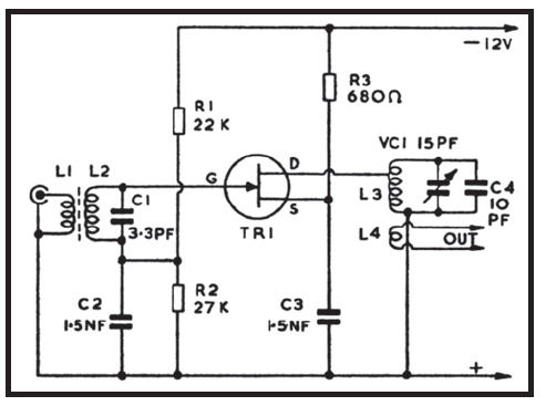
For 144-146MHz reception, L1 is permanently tuned to about 145MHz by T1. Input is to gate 1, from a second tapping, and R3 with the by-pass capacitor C2 provide source bias. Gate 2 is operated at a fixed potential derived from the divider R1/R2. Output from TR1 drain is to the tapping on L2, which is tuned by T2. For a narrow range of frequencies such as the 2m Amateur band, variable tuning is not justified, especially as L1 and L2 do not tune sharply L3 couples to the existing 2m equipment - generally a converter working into a lower frequency receiver.

L1 is wound with 18swg or similar stout wire, enamelled or tinned copper. It has five turns and is tapped at one turn from the upper end in Figure 4 for G1, and two turns from the grounded end for the aerial. The winding is 5/16th in in diameter and turns are spaced so that the coil is ½in long. L2 is wound in the same way with five turns, but is ¾in long and has a centre tap for the drain. L3 consists of a single turn of insulated wire, wound over the lower end of L2.

When building VHF units of this and similar type, a layout permitting short radio frequency and by-pass return connections will be required, and Figure 4B shows a layout for Figure 4. (Note that TR1 is shown from the top.) A printed circuit can be prepared to take the components, or plain perforated board (0.15in matrix) can be used, wired below. It is convenient to insert pins to take L1 and L2. A small aluminium box will house the amplifier, and this allows the co-axial aerial and output sockets to be mounted as shown.

The screen to divide the box into two sections, to separate gate 1 and drain coils, can generally be omitted as the layout does not allow much feedback from L2 to L1. Tapping Gate 1 and drain down L1 and L2 also contributes to stability.


A 12v supply is preferred, but this can be 9v if other equipment provides this voltage and is also to supply the amplifier. The amplifier can be self-contained if a battery is included in the box, with on-off switch in series.

The bolts MC pass through the board and box, so that they can provide a ground return, and they require spacers or lock nuts.

Should a resonant dipper be available, or be constructed as shown later, this will allow L1 and L2 to be set to about 145MHz. If the coils are made exactly as described, adjustment of T1 and T2 should give resonance in the 2m band. However, slight changes in the length of leads, and similar points which arise in construction, can influence the frequency. So should either trimmer, be fully open, stretch the associated coil slightly to separate its turns. On the other hand, if either trimmer is fully closed, compress the coils to bring the turns nearer together. It is possible to experiment with the taps, for best individual results, if the coils are wound with tinned copper wire. Resonance can later be checked when signals are being received through the amplifier. To do this, or tune with no dipper, adjust the trimmers (and coils if necessary as mentioned) for best volume.