The use of a 2N5459 or other general purpose RF type FET in the circuit in Figure 34 will be found to give very good results. This circuit provides very little loading for the intermediate frequency transformer. Current drain is very small typically under ½mA - and a 6v to 12v supply is satisfactory. It should be well smoothed, though C2 and R2 will be helpful in avoiding ripple here.
When this type of detector is fitted in an existing receiver, VR1 will be present, and it is not essential that the value is as in Figure 34. In some home built or other receivers, this may be found to be an easy way of boosting performance. The final IFT will usually need slight realignment. In general, there is some latitude in all the component values.

Superregenerative receivers offer high sensitivity, with a very simple circuit when compared to a superhet. Their main limitations lie in the relatively low selectivity, and the superregenerative hiss produced. However, on some of the HF-bands, where a simple receiver is required, such circuits are still practical and can have enough selectivity. The, regenerative hiss also ceases, when a carrier or AM signal is tuned in.
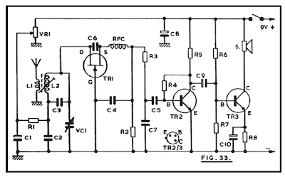
A circuit such as that in Figure 33 can be assembled easily in a small box, and has a range of many miles from even a low powered transmitter. It is most suitable for field and intermittent use, where no interference is likely to arise from it.
L1 couples the whip aerial to the tuning inductor L2. It is quite practical to add an RF stage, using one of the circuits shown earlier, to reduce radiation. VC 1, with the fixed capacitor C3, allows the Whole of the 28MHz band to be covered easily.
TR1 is the superregenerative detector, and a 2N5459 is suggested as allowing smoothest control on these frequencies. However,various VHF FETs will be found to work reasonably well, though it may be necessary to change the value of C6, or omit this item or fit a preset of about 5pF maximum value. VR1 controls regeneration, and quenching is obtained by the correct choice of resistor and capacitor values here.

TR2 is the first audio amplifier, followed by TR3, which will operate a 2½in speaker incorporated in the equipment. A more complete audio amplifier is scarcely justified, though it can of course be used.
L1 and L2 are wound on a 5mm diameter cored former. It is necessary that the core is of material suitable for 30MHz and higher frequencies. L2 has fourteen turns of 32swg enamelled wire, side by side near the top of the former. L1 consists of 6 turns, spaced 1/8in from the grounded end of L2. Too tight aerial coupling may prevent superregeneration.
L1/L2, C3, VC1, TR1 and associated items should be grouped close together, so that short leads are possible. The two AF stages are a little clear of TR1. The RF choke is wound with 42swg wire, on a 7mm or similar insulated rods sufficient turns being used to form a solenoid 7/8in long. The winding should not be doped or varnished, though small touches of adhesive can be used at the ends, as with L1 and L2.
A telescopic aerial which extends to 20 to 30in or so, fitted to the receiver, will be most convenient for portable use. When VR1 is rotated a quite loud hissing should be heard from the receiver. If this does not arise, L1 may be too near L2, or C6 may be of unsuitable value, or TR1 could be a type not intended for these frequencies. Assuming that the receiver will be used in conjunction with an amateur transmitter operating in the 28MHz band, set the core of L2 so that signals fall at about the centre of the range obtained with VC1. VR1 may be adjusted for best results with weak signals, but its setting is relatively uncritical. No hiss or oscillation will accompany normal reception.
Where an alternative and more powerful amplifier is used, VR1 must be fed from an adequately decoupled supply line.
Figure 32 is the circuit of an easily made amplified diode receiver. VC1 may be an ordinary size 500pF or similar air spaced tuning capacitor; or a miniature component if all dimensions are to be kept as small as possible. The tuning coil can have about fifty turns of 26swg to 34swg wire, on a ferrite rod, similar to that described for Figure 31. Or existing medium wave coils may be used. The windings intended for MW transistor portables have a relatively high inductance, and VC1 can then be about 200pF.
 For other than short aerials, it is useful to have tappings, as in Figure 32, to allow sharper tuning. These taps may be at about the middle of the winding, and one quarter the total number of turns from the earthed end. Some coils may have a primary, or aerial coupling winding, which can be used instead.
Component values are not very critical. The detector diode D1 would normally work into a load of a few hundred thousand ohms, such as could be provided by a 270k resistor across C1, but this will be found of little practical significance here.
The 2N3819 and other audio or general purpose FETs will be suitable. Very good results can be expected from a medium or high impedance headset, as for Figure 31.
With crystal earpieces, which cannot be employed directly in the drain circuit, R3 and C4 may be added. The earpiece is then used between C4 and the negative line. This will also allow resistance capacitor coupling into an amplifier for loudspeaker reception. A 9v supply is preferred when R3 is present, but this depends also on the volume required.
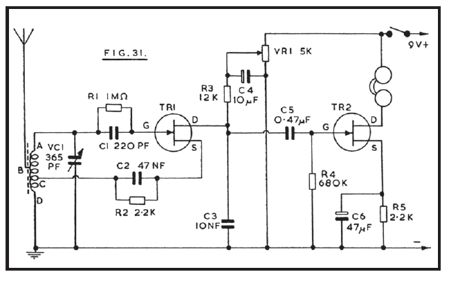
Figure 31 is a circuit giving good headphone reception for persons listening, and it can if wished be constructed as a miniature receiver with a short throw out aerial. Alternatively, it can be used with reduced range by relying on the ferrite rod alone for signal pick-up.
TR1 is the detector, and regeneration is obtained by tapping the source up the tuning coil. The use of regeneration greatly improves selectivity, and also sensitivity to weak signals. The potentiometer VR1 allows manual adjustment of the drain potential of TR1, and so acts as a regeneration control.
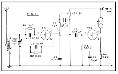
Audio output from TR1 is coupled to TR2 by C5. This FET is an audio amplifier, operating the headphones. A complete headset is preferable for general listening, and phones of about 500 ohms DC resistance, or about 2k impedance, will give very good results here. If a miniature earpiece is wanted, this should be a medium or high impedance magnetic unit. A crystal earpiece will require resistance capacity coupling, Figure 32.
The tuning inductor is fifty turns of 26swg wire, on a ferrite rod about 5in x 3/8in. If the turns are wound on a thin card sleeve which can be moved on the rod, this will allow adjustment of band coverage. The winding begins at A, and aerial tapping B is at about twenty-five turns. D is the grounded end of the coil. The best position of the tapping C depends somewhat on the actual FET, on the battery voltage, and on whether the receiver is to be used with an external aerial wire or not. Should the tapping C be too near to end D, no regeneration will be obtained, or regeneration will be weak, even with VR1 rotated for maximum voltage. On the other hand, with too many turns between C and D, oscillation will begin with VR1 only slightly advanced, and signals will be weak.
Best results are expected when regeneration begins smoothly, with VR1 about half way through its rotation. It was found that only one to two turns were required between C and D. As changing the whole coil by a turn or so has little practical effect on frequency coverage, the best method is to make C two turns from D. Then if necessary unwind half a turn or more at D.
When regeneration is obtained, a heterodyne will be heard if the receiver is tuned through a transmission. VR1 should then be turned back very slightly. Maximum possible sensitivity is achieved when TR1 is almost in the oscillating condition. VR1 has to be set to suit the frequency tuned by VC1, so that final critical adjustment can be made. It is useless to regard VR1 as a gain control, and set it at maximum.
A metal case is suitable where an external aerial wire will be used. Where the ferrite rod only will be employed, for local signals, the box or case must be of plastic or other insulating material.
A tuner allows radio reception with the aid of any amplifier, so can greatly increase the scope of the latter. In many cases reception of this kind will be of the more local or powerful stations only and a superhet tuner is not then necessary. The circuit in Figure 30 has a single FET as RF stage, followed by diode detector, and is intended for medium wave reception.
L1 is the aerial coil, and L2 the diode coil, and a matched pair of TRF inductors is required here. Pin numbering is for the Denco (Clacton) valve type coils, “Blue” Range 2 for the aerial position, and “Yellow” Range 2 for the diode stage. VC1/VC2 maybe a 2 x 310pF or 2 x 365pF ganged capacitor, with integral trimmers. Separate 50pF trimmers may be added if these are not present.
It is probable that other matched coils, such as those used in a discarded valve receiver, would be found satisfactory here.
Numerous general purpose RF FETs will be found suitable in this circuit. The constructional layout should separate L1 and L2, in the way explained for earlier RF amplifiers. Coupling between L2 and L1 causes the stage to oscillate, so that proper reception is impossible.
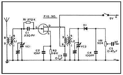
Where the amplifier has an input volume control which will be used, VR1 can be omitted. Audio output from the tuner is at a much higher level, than that from a pick-up or microphone. It may thus be convenient to retain VR1 so that output can easily be set at a suitable level.
Operation is from a separate 9v battery, so that the tuner can be connected to any amplifier without needing to draw power from the latter. It would in many cases be a straightforward matter to arrange that current for the tuner is derived from the amplifier.
Such a tuner will normally be used with a transistor amplifier. It can, of course, operate with valve amplifiers, but it is essential to refer to the earlier notes on safety, in such circumstances.
The aerial may be indoors or outdoors, depending on signal pick-up required, freedom or otherwise from local interference, and similar points. The cores of L1 and L2, and trimmers for VC1 and VC2, are initially set in approximately similar positions. Subsequently adjust the trimmers at a quite high frequency in the band covered, and the coil cores at a quite low frequency, for best results. As these settings interact to some extent, repeat the adjustments a few times.